Login to view this content
Join Blender Studio for just €11.50/month and get instant access to all of our training and film assets!

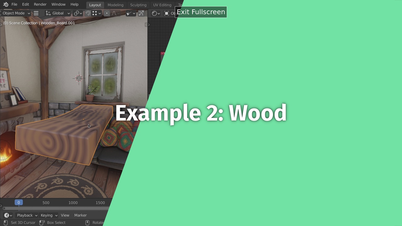
Wood (Chapter 3+)
In this workflow example we go a step further and take a look at the dynamic wood shader. It is aimed at a level after finishing chapter 3 of the course.
30 comments

I'm so excited to do small experiments now, I wanted to try to add distortion to the dust diffuse shader, I think I made a mistake by using the object coordinates for the noise texture connected to linear light and then to the factor of the mix shader.
@Keshav Chaurasia If you are using the setup to blend with the z coordinate, you can also add the noise before applying the map range operation
@Simon Thommes Thanks! it worked!

This is the most complex shader I've ever made! And I really understood what I was doing! Instead of using the pointiness, I use a Dot Product of the Bevel node and Normal from the Geometry node (not my invention). What is your preference, Sir Simon?
@Benjamin Bass I'm glad to hear that! The method depends a bit on the geometry for more organic shapes and high poly count the pointiness works a bit better from my experience. But the method using Bevel works great for sharp edges and low poly count

In order to get more randomness on the final output, you can add a Mapping node in front of the Distortion frame nodes and use Object Info>Random to control the location of the texture coordinates. This gives a very good result which can be adjusted with further Math nodes. THANKS! This was a great tutorial!

I started doing this object as a cube with a bevel modifier. I could not get the object to look like what you had up to the point where you added the Ping-pong node...then I eventually figured out that I needed to scale the object by uniformly scaling all the edges at the same time in Edit Mode rather than scaling the entire cube in object mode. Wasn't easy to figure out 😭
@Luis Saybe Correct, I forgot to mention that in the video as I simply intended to use the example geometry. Generally it is always a good idea to do scaling operations like this in edit mode and keep the object scale for operations that don't regard the shape of the object itself.

For my normals I get the opposite effect as in this screenshot https://imgur.com/a/bjf5gAW
@Leslie Solorzano My guess would be that the object you are using has inverted normals. Have you tried your material on a simple default cube? Otherwise you can also compare the node setup with the one from the example scene.
@Simon Thommes The cube looks the same, I actually checked the normals by showing face orinetation and they were all blue. I imported the material from the .blend that you provide and it looks different, I don't know if it has to do with the size or shape of mi object. But it doesn't matter, the important ting was to learn the method

why do you use separate object co-ordinate's? can it not come from same node? what are the reasons of a seperate flow?
@jamesrossbond You can use the same node, there is no difference in how it works. The reason I am using seperate nodes is for node-tree readability. It is more structured when logically disconnected parts of the shader use separate coordinate inputs, that also allows to change the used coordinates individually later on.

When do all steps up to 03:51 with cube I created on my own the texture coordinates seems to differ from the cube of the example scene. I created a new file,then created a cube, changed the dimensions that it looks more like a board, the added the Texture coordinates as described. Then I appended the board from the sample scene. With the same shading nodes it looks different from the colors which means there must be something different with the coordinates. Please check: https://www.dropbox.com/s/f705tp39n26p8qm/woodenboard_1.blend?dl=0 How come? What is special about the board from the example scene?
*@Michael Schwarz* When you scale down the cube in object mode, that means that the object coordiantes are squashed or stretched along with it. Sometimes that is useful, but here you want the coordinates to be unaffected from scale. To achieve that you can either apply the scale of the object by pressing CTRL+A or scaling the cube down in edit mode in the first place.
*@Simon Thommes* Thank you very much! I just overlooked the scaling factors for x-y-z I had for my board.

I absolutely love these practical examples, for me it's the only way to learn, bouncing back to the theory videos with the context of trying things out (over and over again).

Excellent. course, I think I actually got most of this part. The only thing I did different is added a noise texture to the dirt gradient texture to break up the dirt a bit.

hello,
my "pointiness" doesn't "push" the value to the edges of my wood object: https://photos.app.goo.gl/Uduwswz773BgPK468
here is my .blend file: https://drive.google.com/file/d/1dBamVEsfBWJx5Xg0C5SbyXnC3X25dWhd/view?usp=sharing
*@Huân Lê-Vương* The problem is that your geometry does not have any actual curvature. To make the most of the pointiness feature, you should add a bevel to the edges, for example with a modifier. You can take a look at the objects in the example scene.
*@Simon Thommes* thanks.
it took me a while to understand the "length" part :v "square root" is involved so that's why we have the radial?
*@Huân Lê-Vương* The lenght operation simply gives you the length of the vector that you plug in. Mathematically that is sqrt(x^2+y^2+z^2), but here that does not really matter. What is important is only that for a coordinate map that gives you the distance from the center, or a radial gradient from the inside out.
(deleted, i know how)
(deleted)
*@Simon Thommes* ok, thanks!

That's a clever way to use object and textures coordinates instead of wood and gradient textures. So in general, do you only use the noise texture and none of the other hard-coded ones? Thanks a lot for the course, can't wait for the other chapters.
*@Mathieu Quiblier* Yes, I usually make my own base textures. That gives me the option to use all of the information in between and have exactly the features that I need and most of the time it does not take so long to set them up. Only noise textures are really hard to recreate, so I use those directly, I talk about that in the chapter about noises. There are exceptions though, for example the magic texture is really nice to create cheap and simple textile patterns.

Kindly tell about math node. I dont understand things like smooth minimum and maximum...After repeated plays I have understood many things...
*@Abhirama Gopala Dasa* I am not exactly sure I understand you correctly. The workflow examples are meant to support the main content of the chapters to develop a deeper understanding of the topics that have been touched and draw connections. I go over how to use smooth minimum and maximum to combine value maps in chapter 2.4 about texture composition.
Join to leave a comment.